|
|
|
|
|
|
|
|
|
|
|
|
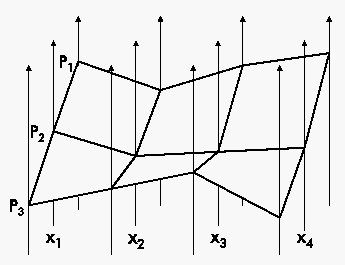
The approach of parallel coordinates is defined by the perpendicular equidistantly arranged axes, which are connected by a polyline, that represents one point. The dimension of the visualized points has no upper limit and so this method is fitted very well for the visualization of high-dimenional data. For visualizing high-dimensional flows parallel coordinates have the drawback, that the information about the order of the points is lost.

The extension of parallel coordinates into the third spatial axis, Extruded Parallel Coordinates, simulates the flow by moving the parallel coordinate-system along the third spatial axis after each plotting of a sampled point of the trajectory. Additionally each sample point, i.e. polyline, is connected with the preceding point, so that the trajectory appears as a surface consisting of rectangles. So the state of the DS at each point of time can be determined easily, as the third spatial axis represents the time of the DS.
With this visualization technique it is possible to investigate characteristics of the trajectory, like correlations and clustering. Another advantage of EPC is that all variables are visualized equally and the characteristics like convergence or divergence of the high dimensional DS can be observed at once. Furthermore it is also possible to visualize a whole class of DS by inserting more than one trajectory into the EPC system.
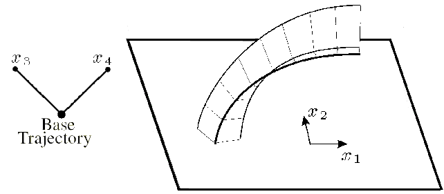
This technique can be interpreted as an extension of a 2 dimensional trajectory plot on a plane. Two of the n variables are chosen to define the plot of the base trajectory on the base plane. As the 2 dimensional trajectory is mapped into a 2 dimensional subspace, a third dimension is left to represent the other n-2 variables. This is done by extending the base trajectory with wings, whose lengths indicate the remaining n-2 dimensions. The angles between the base plane and the wings are constant along the whole trajectory and they should be chosen, so that the angles between the wings and the base plane are equal. As example, if on the trajectory 3 wings should be linked, then the wings' angles should be -PI/2, 0 and +PI/2.

Basically, each number of dimension greater than 1 can be mapped into LWW. In practical use, occlusion will arise with higher dimensions. Therefore the wings could be drawn transparent or highlighted with textures. Another point is, that very self-intersecting trajectories lead to occlusion even with dimensions not much more than 4. A way to avoid this would be to map negative values of the variables on the extended wing under the base plane, or simply scale the length of the wings to a smaller value.
An advantage of the technique is the similarity to the common 2D streamline plots, and therefore is easily understandable for most observers. Following the trajectory all n dimensions of the system can be observed at once, as they are encoded directly at the trajectory.
3. Three-dimensional Parallel
Coordinates (TDC)
To display a high-dimensional point with parallel coordinates, each single variable is mapped on one-dimensional lines, i.e. the coordinate axes, which are placed in parallel, and the points on the coordinate axes are connected by lines, which results in a polyline. TDC is basically the same method, with the difference that not a single variable is mapped into a one-dimensional line, but two variables are mapped into a 2D plane. Then all the 2D trajectories, each on another plane, are connected.
The connection of the trajectories defines surfaces between each two planes. Note that the planes may not be placed parallel to each other, they even can coincide. To avoid occlusion the surfaces should have high transparency or better should only be approximated by lines. As with LWW self-intersection of trajectories can lead to heavy occlusion and therefore to confusion of the observer.
As TDC are composed by 2D planes the DS should have an even number of dimensions to fit into this technique. A possibility for systems with an odd dimension count is to represent one of the plane only as a line, or take one of the variables twice, to obtain another 2D~trajectory. Another way to use TDC is to create a bifurcation diagram of 2-dimensional DS. The trajectory of each plane is defined by a pair of equations, which only differ in a certain parameter value.
Like with EPC more than one trajectory can be visualized at once. When a set of initial values for at least one dimension is given, the surfaces between the planes are extended to volumes, where convergent and divergent regions are indicated by the thickness of the volumes.
Back to home.
|
|
|
|
|
|