DVR Renderer
for Dichromats
Course Visualization 2
Iliyana Kirkova (0226860, 532), Katharina Krösl (0325089, 932)
Vienna UT, 2013
This is the
documentation of our direct volume rendering program for dichromats created in
2013. Our implementation is based on the paper “An Efficient Direct Volume
Rendering Approach for Dichromats” by Chen et al.
Links:
Purpose
Volume
Visualization is a common tool for communication and analysis, but it does not
provide suitable support for users with color vision deficiency (CVD). This
problem affects a high percentage of the population worldwide. People with
normal vision, or trichromats, have three types of cones in their eyes that
respond to long (L), medium (M) or short (S) wavelengths. The responsivity
spectra of the cones define the LMS color space. Dichromats have only two types
of cones, which means that their LMS color space is much smaller than that of a
person with normal vision. Therefore people with CVD are not always able to
distinguish between two different colors
and may miss important visual classification in the results, provided by
the common DVR. The paper of Chen et al[1]. suggests extending the components
of the DVR in order to allow user with normal vision to generate results
perceivable for dichromats. Their algortihm builds upon the recoloring scheme
first presented by Kuhn et al.[2] and applies the image recoloring technique of
Machado and Oliveira [3] to first recolor an image so the resulting colors are
located in the reduced color space for dichromats. Then the recolored image is
used to optimize the Transfer Function for DVR and incorporates CVD-friendly
color blending and luminance consistency. You can find a short summary of the
paper of Chen et. al. in the "Links"- section above.
Funktionality
Our Program
can load a 3D data set and render it using direct volume rendering (DVR). It is
also possible to step through the volume slice by slice in all 3 coordinate
axis direction. A color transfer function allows to color the Volume. The user
can chose whether to use the density values provided by the dataset as alpha
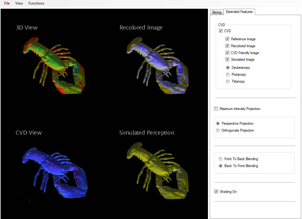
values or the ones of the transfer function. The Extende Feature set consist of
multiple small optional changes for the rendering and the CVD mode. In
splitscreen the original DVR, a the simulated image, the recolored image and
the CVD friedly image can by displayed.
The
simulated image simulates the perception of the original DVR for dichromats.
The recolord image shows the recoloring of the original image using the
technique presented by Machado and Oliveira [3].
Implementation
We
implemented the method presented in XNA 4.0 using c# as programming language
and HLSL as shader language. Furthermore we use Windows Forms for our GUI and
the ILNumerics Library to solve line equations. Our implementation is based on
a volume renderer we created for DVR and Slicing of Volumes.
Our
Implementation works as follows:
First a
volume dataset is loaded and rendered using our DVR. When recoloring is
activated the following steps are processed:
Recoloring
Convert RGB colorspace to
L*a*b* colorspace
The image
is converted from the RGB color space to the L*a*b* color space.
1. gamma correction
2. convert from RGB to XYZ
3. convert from XYZ to L*a*b*
4. rotate colors around L* axis
according to the angle between the b* -plane and the reduced LMS color space of
the specified color vision deficiency
Calculate Contrast Loss
The
contrast loss on the chromaticity plane for people with CVD is calculated.
This shader
gets L*a*b* colors as input.
For each
pixel it takes the color of a neighbour coordinate indicated by a gaussian
noise texture (using gaussian pairing).
1. projects colors and neighbour colors
to b* plane
2. compares distances between actual
color and projected colors
3. calculate relative loss of color
contrast (using distance in L*a*b* space)
|| Pixel_proj - Neighbour_proj
||
loss = 1- ------------------------------------------
|| Pixel
- Neighbour ||
4. save the weighted direction of loss
on the chromaticity plane
Since we
preserve the lightness coordinate (i.e., L*) of the original colors to avoid
polarity reversal, it is sufficient to compute the direction that maximizes
contrast loss on the chromaticity plane.
Calculate Predominant
Component
Input are
the weighted directions of contrast loss.
This shader
computes the predominant component for the whole image by summing up all
weighted directions. It then returns the matrix
M = [a*a a*b; b*a b*b].
Calculate Eigen Vector
We do a
calculation of loss of color contrast (in a least-squares sense) in the
chromaticity plane.
The input
is the predominant componenet of the calculated color contrast loss. This
shader computes the main Eigen Vector of matrix M = [a*a a*b; b*a b*b]
corresponding to greatest Eigen Value.
Poject colors on plane
minimizing contrast loss
Colors of
the original image in L*a*b* color space are projected onto the LMS plane.
This shader
performs an orthographic projection of the original colors onto the plane
defined by the vectors L* and the main Eigen Vector of the image. We preserve
L* and do the projection only in 2D using the dot product of vector (a*, b*)
and the main Eigen Vector(y, z). The length of the projected vector is the new
b* coordinate. This represents a rotation around L* onto the b* plane.
Compute max projection
effect
This shader
computes the absolute maximal b* coordinate of the projected colors for later
contrast enhancement
Contrast enhancement
This shader
enhances the contrast in b* direction of the projected colors by dividing by
the absolut greatest length of the b* coordinate of all the projected colors.
This results in a maximum range along the b* plane.
Convert L*a*b* colorspace
back to RGB colorspace
The
resulting image of the previous calculations is converted back to the RGB color
space.
1. rotate colors back around L* axis
according to the angle between the b* -plane and the reduced LMS color space of
specified color vision deficiency
2. convert from L*a*b* back to XYZ
3. convert from XYZ back to RGB
4. inverse gamma correction
The
recolord image is then used to optimize the Transfer Function.
Optimizing the Transfer
Function
In this step the result of the recoloring operation is used to define
teh bnew transfer function with cvd-friendly colors. A linear equation set is
defined where the colors of the intended cvd friendly DVR are expressed as a
linear combination of the intended transfer function and weights associated
with the original one. The weights are computed during a ray casting step and
define color, opacity and illumination accumulated for each ray. The linear
system is then solved by using the least-squares method and aims to calculate
an optimized transfer function that will produce DVR as close as possible to
the recolored image. This is achieved by randomly selecting pixels from the
recolored image.
CVD-friendly color
composition
Color Blending
During DVR
with the new transfer function the colos are converted to the L*a*b* color
space as previously described and blended in the reduced LMS color space.
Luminance Consistency
Analog to
the color Blending also the L* coordinate which represents the luminance is
blended in teh reduced LMS color space.
Simulate Perception
To be able
to compare results we also implemented a simulation mode that simulates the
perception of the original DVR for dichromats using an approximation of the Brettel model [4]. In our
implementation we approximate the two half planes of the LMS color space by one
plane in the L*a*b* color space.
Refernces
[1] W.
Chen, W. Chen, and H. Bao. An Efficient Direct Volume Rendering Approach for
Dichromats. IEEE Transactions on Visualization and Computer Graphics, 17(12),
2011.
[2] G. R.
Kuhn, M. M. Oliveira, and L. A. F. Fernandes. An efficient
naturalness-preserving image-recoloring method for dichromats. IEEE
Transactions on Visualization and Computer Graphics, 14(6):1747–1754, 2008.
[3] G. M.
Machado and M. M. Oliveira. Real-time temporal- coherent color contrast
enhancement for dichromats. Computer Graphics Forum, 29(3):933–942, June 2010.
[4] H.
Brettel, F. Vi´enot, and J. D. Mollon. Computerized simulation of color
appearance for dichromats. J. Opt.
Soc. Am. A,
14(10):2647–2655, 1997.
ILNumerics
Library: http://ilnumerics.net/Support_Documentation$GetStarted.html