
On this page we present VStudio, a software framework that offers a state-of-the-art direct volume rendering implementation and combines several techniques providing the user with an advanced interactive volume visualization approach. The introduction gives a brief overview about the framework. For a more complete description about the features, user interface and basic workflow check the corresponding sections below.
IntroductionVStudio is a window-based application compiled to be used on the Microsoft Windows Platform. Written in C++, it is developed using the rich C++ class library and integrated tools for GUI development offered by QT, a cross-platform application framework for desktop and embedded development. While the intuitive GUI is built using Qt Designer, a powerful cross-platform GUI layout and forms builder provided by the toolkit, we also utilize the tight integration with OpenGL for rendering the graphics contents. Using QT´s comfortable OpenGL module for opening an OpenGL display buffer, the application renders the contents using graphics features for 3D visualization provided by the OpenGL API since version 2.0. Notably, we use the OpenGL Shading Language and the related API for the direct volume rendering implementation.
VStudio applies single pass GPU ray casting as the direct volume rendering method of choice. Implemented with a vertex, fragment shader configuration, and inspired by interactive shader development software i.e. FX Composer (NVIDIA), editing, verification, saving, loading and application is - as part of the user interface - interactively supported with immediate feedback. Furthermore, parameters dealing with progressive quality refinement light specification, etc. are available throughout the user interface with changes directly committed and available in the shader code.
The ray casting implementation, as delivered, applies stochastic ray shifting, a single scattering illumination model, optional shadow-ray traversal, and incorporates several acceleration techniques. Interactive transfer function specification by means of versatile gradient editing widgets is facilitated by multi-resolution data histogram charts, which can show traditional histograms as well as histograms obtained by applying iso-surface statistics, which represent the distribution of properties in the volume data more accurately. The results of multiple transfer function lookups (density and gradient magnitude) are combined through arbitrary modulation. The interactive shader editing functionality allows for full customization of this process and furthermore alleviates investigation concerning techniques and data.
Windows 2000 or Windows XP (32bit) as the target platform and a GeForce 8 graphics card supporting Shader Model 3 should sufficiently meet the requirements for execution. After starting the executable file VStudio.exe found in the release folder, the application checks if the required extensions are supported by the target platform and brings up the user interface in case of success. Otherwise it aborts with an error message. The settings.ini file also found in the release folder allows for specifying default startup behavior and data path definition. Deleting this file results in a new default settings file being created at the next startup.
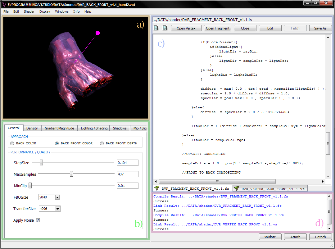
The User Interface is divided into the main menu toolbar, four distinct, resizable regions and a console which logs basic user interaction. Resizing a region works by dragging the border of a region. If the region is at its minimum size, further dragging collapses the region, hence enlarging the adjoining one, which is useful during focusing on shader editing.a) Viewport, b) Property Editor, c) Shader Editor, d) Shader Output Panel
- The Main Menu Toolbar
The entries found in the main menu toolbar permit the importation of volumetric data and saving and opening scenes, which is discussed in the section about the basic workflow.

- The Viewport (a)
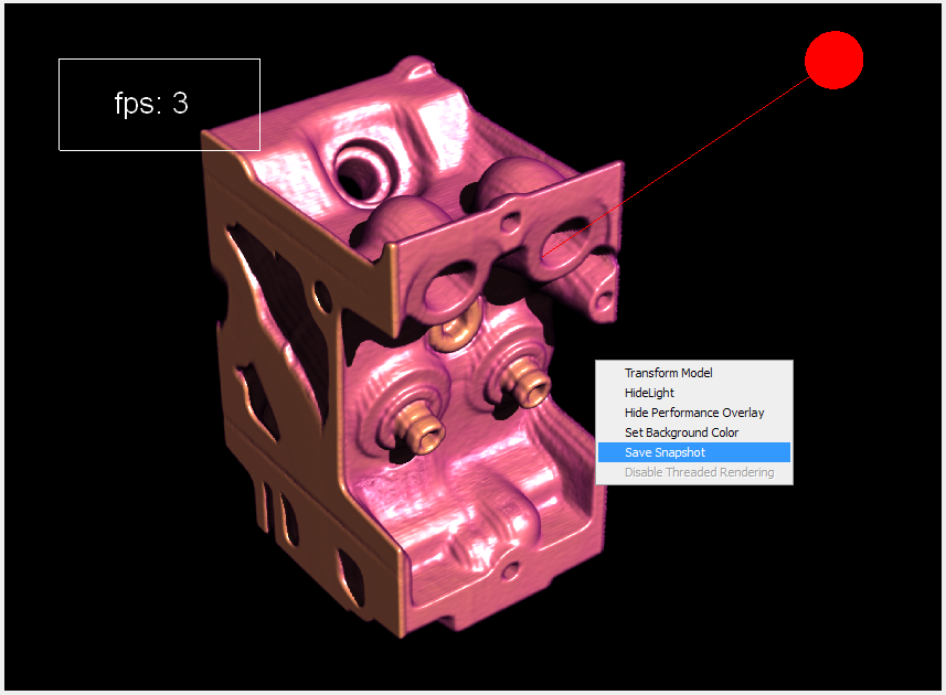
The viewport is a multi-threaded, resizable OpenGL widget which shows the rendition and allows for interactive scene manipulation such as rotating, zooming and panning the volume. Notice that the size of this widget and zooming directly affect performance since the number of per-fragment operations proportionally scales with the size the volume occupies in screen space. LMB down and dragging rotates, MMB down and dragging tracks, LMB + MMB down and dragging dollies and RMB down and dragging changes the field of view. Transforming the light source works in an azimuth, elevation fashion by ALT + LMB down and dragging horizontally and vertically. Furthermore, a context menu, displayable by CTRL + RMB click, provides options for setting the background color, toggling a performance overly, toggling the display of the light source, saving a snapshot and toggling weather the input is used to transform the camera or the volume itself. Double-clicking maximizes the viewport which allows a snapshot to be taken at maximum resolution. The output path is logged by the console and refers to the current scene name. Specifically, a folder named after the scene is created and subsequent screenshots are named and saved suffixed with increasing numbers:
/Data/Snapshots/[Scene Name]/snap[#].bmp
- The Property Editor (b)
The property editor below the viewport groups related properties into tabs.
Most of the editable settings are available in the fragment and vertex shader through uniform variables with corresponding names, which allows for altering their range or completely redefining their use in the shader code.
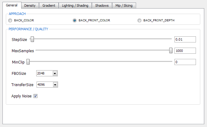
- The General Tab
offers widgets for modifying quality settings. The StepSize Slider allows for progressive quality refinement, as such controlling the spatial distance between sample positions during ray traversal, hence the sampling rate. The MaxSamples Slider permits the limitation of the amount of samples taken along a ray. The Minclip Slider allows for discarding samples with values below a certain threshold. The FBOSize controls the resolution of the textures into which ray entry and exit positions are rendered for lookup in the fragment shader in order to compute the ray directions for each fragment. The TransferSize controls the resolution of the texture-based lookup tables implementing the transfer functions. The checkbox Apply Noise toggles stochastic ray-shifting.
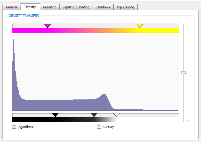
- The Density Tab
shows the distribution of density values in the current volume and allows for transfer function specification based on this quantity. The top gradient editing widget facilitates color specification and the bottom gradient editing widget opacity specification. Double-clicking the white bar to choose a color inserts a tab-stop at the respective position which can be moved left to right in order to further refine the position. Right-clicking a tab-stop removes it. White corresponds to opaque and black to transparent. The histogram in the center can be zoomed by LMB down and dragging and reset by RMB click in this area. The histogram should be interpreted as follows: the horizontal axis denotes density values in the range 0-1quantized into a specified number of buckets controlled by the slider to the right of the histogram, while the vertical axis represents the relative occurrences of these values. Furthermore, the logarithmic check box at the bottom allows for display at a logarithmic scale.
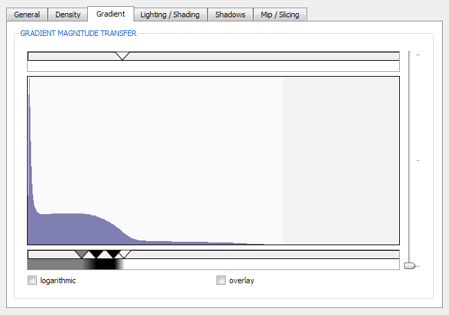
- The Gradient Magnitude Tab
provides the same features as the density tab; however, it shows the distribution of gradient magnitude values contained in the current volume instead. Specifying the transfer function to be “white” in color and opacity has no effect on the results of the density transfer function specification. The results obtained by arbitrary specification, however, as in the above case depend on the transfer function application implementation in the shader code.
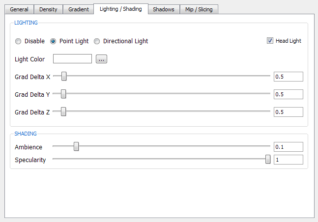
- The Lighting/Shading Tab
offers controls for lighting and shading. Lighting computation can be turned off altogether or specified to consider illumination from either a point or directional light source. Checking the Head Light check box parents the light source to the camera position. Though transformation of the light source is possible as described above, the light will pop back into the position when done. Light color can be chosen by pressing the LightColor button. The GradDelta Sliders control the offset distance to the sample position that is taken for gradient computation for each individual axis. The Ambience and Specularity Sliders control the glossiness and ambient appearance of the surfaces rendered.
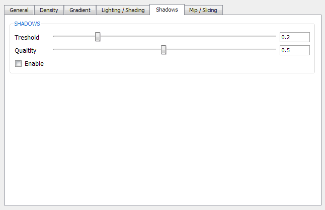
- The Shadows Tab
offers controls for enabling shadow computation using brute force shadow-ray traversal. For each sample a shadow ray is cast towards the light source and sampled until occluding matter of density, specified by the Threshold parameter is encountered. The Quality slider controls the number of samples taken during this traversal in the range 0-100.
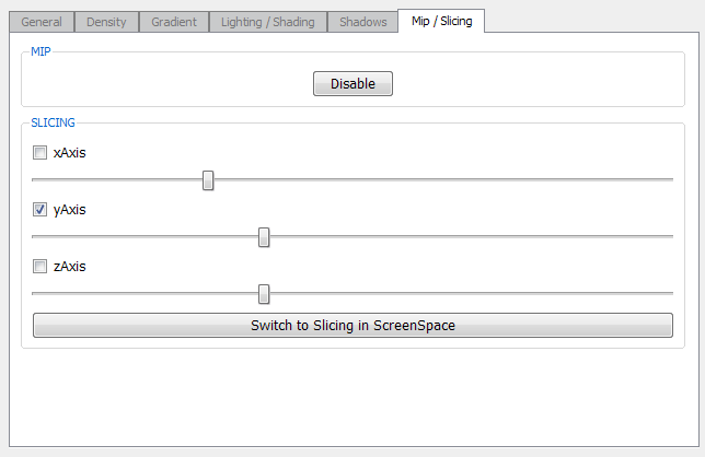
- The Mip/Slicing Tab
allows for enabling a maximum intensity projection display of the current volume. When switching to this mode by pressing the Enable button, the currently linked and used program (if any) is temporarily switched to a shader implementation which can be found in the Data/Shader/ directory. It can be modified or replaced all together. Use the entry in the settings.ini file in order to specify your own vertex/fragment shader pair implementation for MIP. Slicing in the three major axis is enabled by checking the corresponding axis checkbox and moving the sliders. The last button in the Slicing Group allows for switching from slicing in view space to slicing in object space.
-
The Shader Editor and Shader Output Panel (c)(d)
The right portion of the GUI comprises the interactive shader editing features of the framework. The button row in the top allows for creating and opening multiple shader text files for simultaneous editing in the tab-styled text area below. Each file is displayed on a separate tab identified by the filename and a symbol exposing the state and type of the shader. Subsequent actions such as saving, closing, external editing, validating, attaching and detaching, which will be described below, operate on the shader currently displayed by the active tab.
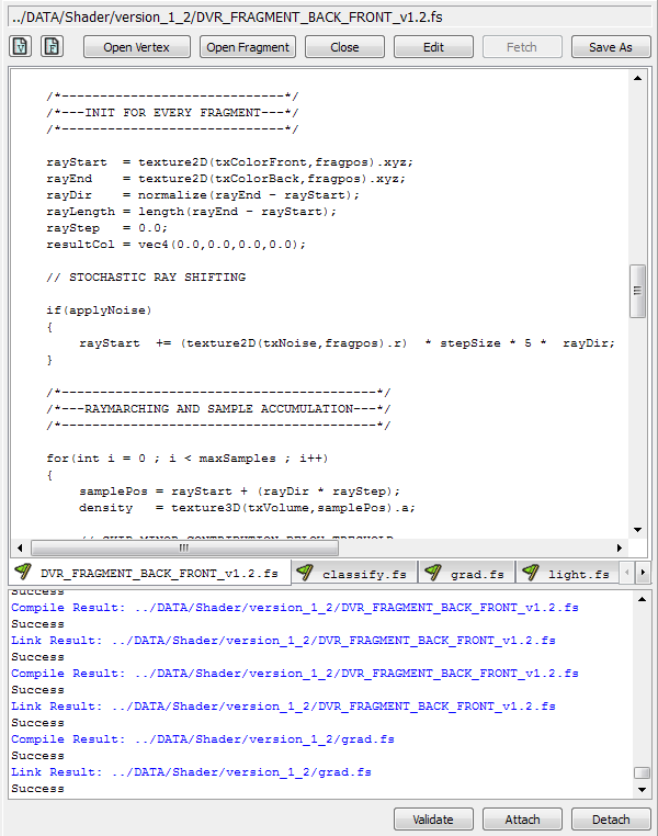
- The Save As Button
opens a dialog box for saving the current shader file to a specified location on the hard drive. The predefined file extension characterizes the type of shader and is used to recognize it as such when opening: “.vs” for vertex shader, “.fs” for fragment shader.
- The Edit and Fetch Buttons
in combination allow for editing of the current file in an external text editor, which may provide advanced features such as syntax highlighting and programming guidance. Usage requires the absolute path of the external executable and parameters to be specified in the settings.ini file. Note that this feature was tested solely with Ultra Edit, which offers syntax highlighting for GLSL and may not work with arbitrary external text editors. Edit temporarily saves the file and opens it in the external application; Fetch brings the edited and externally saved(!) file back into VStudio.
- The Open Vertex / Fragment Buttons
open a file browser for browsing and bringing in a text based shader file
- The Symbols V and F
create a new shader tab within the GUI
- The Validate Button
allows for checking whether the current GLSL shader is written according to the OpenGL Shading Language specification by executing an external application called “glslvalidate” from 3DLabs. The output of the check is captured and displayed in the shader output panel.
- The Attach Button
compiles the current shader and tries to relink the GLSL program together with all the other shaders possibly already attached to it in a previous step, which can be seen by looking at the symbols of the tabs respectively showing a red or green flag. If the linking fails, the error string returned from the API is output in the shader output panel. Once attached, the tab displays a flag symbol in either green or red depending on the result.
- The Detach Button
detaches the current shader and tries to relink the program without that particular shader. If the linking fails, the error string returned from the API is output in the shader output panel. Once detached, the flag symbol changes to the previous symbol characterizing the type of shader showing a “V” or “F” respectively.
In order to get started immediately, when the application starts, a scene file named "startup.vst" is loaded by default.
It references and links all the required shaders in version 1.2. Just use
File/Import/Volume to load a volumetric data file.
In case you want to turn off this behavior, edit the settings.ini file and clear out the value at the entry sceneAtStartup.
Then however you have to take the following actions described next:
Assuming a fresh startup of the application has occurred, the basic workflow for investigating a volumetric dataset with the delivered ray casting implementation involves the following tasks executed in arbitrary order.
-
Use File/Import/Volume to browse and load a volumetric data file.
The application shows a modal dialog box giving feedback about the progress of the advanced ACC histogram calculation, which is automatically initiated for density and gradient magnitude. If you choose to abort it, only the traditional histogram for density is calculated. MIP and SLICING can be immediately used without the need to import any shaders. You can download datasets provided at the LU Visualisierung webpage:
http://www.cg.tuwien.ac.at/courses/Visualisierung/Angaben/Bsp1.html
-
Use Shader/Apply Vertex Shader on the Main Menu Toolbar to browse, load and attach a vertex shader.
Basically, it yields the same result as using Open Vertex and Attach in the shader editing region.
The current implementation, recognizing all the features provided by the user interface, uses the shader pair configuration in version 1.2. The current vertex shader is located in the Data/Shader/version_1_2 folder named:
- DVR_VERTEX_BACK_FRONT_v1.2.vs
- Use Shader/Apply Fragment Shader on the Main Menu Toolbar to browse, load and attach (a) fragment shader(s). Basically, it yields the same as using Open Fragment and Attach in the shader editing region.
The current implementation, recognizing all the features provided by the user interface, uses the shader pair configuration in version 1.2. The current fragment shader implementation is located in the Data/Shader/version_1_2 folder consisting of several separate files named :
- DVR_FRAGMENT_BACK_FRONT_v1.2.fs
- classify.fs
- grad.fs
- light.fs
- shadow.fs
DVR_FRAGMENT_BACK_FRONT_v1.2.fs contains the main entry point and uses functions defined in the other shader files. As soon as all of the above shader files are attached, linking will succeed.
At any time the current state of the application can be saved and restored by loading the scene file later.
- Use File/Save or File/Save As to capture the state of the application and save it to a file.
The scene file is a text- based file which saves several aspects of the current working environment. Exploring a scene file (*.vst) with a text editor shows the information grouped in an intuitive way with meaningful names one can easily associate. Notice that the currently opened shader files are referenced by filename and are not specific to a scene.
The saved state includes:
- Camera Settings and Camera Position
- The Referenced Volume
- Viewport Visibility Settings
- Lighting Parameters and Light Position
- Rendering Quality and Performance Settings
- Shadow Settings
- Density and Gradient Magnitude Transfer Function Specification
- The Referenced and Currently Linked Shaders
- Use File/Open or File/Open Recent to load a previously saved scene.
Open recent provides a list of the last four scenes previously worked on. The settings.ini file keeps track of this list and also allows one to specify that a scene be loaded at startup.
VStudio expects a file, containing the volumetric data to be imported to follow a special structure.
Though the original data values should be distributed using the range corresponding to the bit depth, VStudio expands the data value range during import. The following extensions are supported:
| *.dat | The actual scalar data is 16 bit and a 6 byte header preceding the data block must specify the dimension of the volume in the following order:
|
| *.vol8 *.vol12 *.vol16 |
The extension must match the bit depth, the actual scalar data follows and a 12 byte header preceding the data block must specify the volume, providing information in the following order: (all values must be in the range 1- 4096)
|
The main features of VStudio are:
- Application
- Interactive Shader Editing, Development and Application within the GUI
- MultiThreaded
- Scene File based Working Environment
- Interactive Navigation and Light Source Transformation
- Zoomable Histograms
- Versatile Color Gradient Editing Widgets
- Snapshot Feature
- Volume Rendering
- Single Pass GPU Ray Casting (exposed and customizable due to interactive shader editing)
- Active-Cell-Count Histogram Computation
- Interactive Separable Transfer Function Specification for Density and Gradient Magnitude
- Blinn Lighting Model (Point and Directional Light Sources)
- Early Ray Termination
- Progressive Refinement
- Stochastic Ray Shifting
- Brute Force Shadow-Ray Traversal
- Maximum Intensity Projection
- Slicing in View and Object Space
Robert Hausmair
Student at the Technical University Vienna, Austria
e9709998@student.tuwien.ac.at